DV2 - Binary inputs and outputs module
Basic description of the DV2 module
The external I/O module DV2 expands the number of binary inputs and relay outputs of the FIEDLER AMS control units. Up to two external DV2 modules can be connected to one M4016 unit via the RS485 interface, up to 10 DV2 modules can be connected to H3, H7 series units

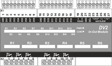
Connection of DV2 module terminals
One DV2 module contains 16 binary inputs switched against the earth terminal and 6 relay outputs with 250V / 6A switching contacts. The closing of the binary input as well as the closing of the switching contact of the relay is signaled by the lighting of the respective LED diode.
The supply voltage of the DV2 module can range from 12 to 24V DC. The current consumption when all six relays are closed is less than 250 mA.
The M4016 control unit connected via a suitably routed RS485 serial interface (signal line without concurrence with power line, twisted pair wires) can be up to 500 m away from the DV2 module.
16 binary inputs
The inputs of the DV2 module are activated by switching the corresponding input with the GND ground terminal. An auxiliary potential-free contactor, a free relay contact or a sensor with an open collector can be used for switching. In the open state, the input voltage is 5V DC and the closing current is less than 5 mA.
The binary inputs of the DV2 module can be used for monitoring motor movements and faults, reading operating hours, checking inputs to the building, reading the limit states of servo dampers, etc.
Unlike the binary inputs on the connection board of the M4016 unit, however, the DV2 inputs are not combined pulse-binary inputs, so it is not possible to connect an output to them, for example, from a pulse water meter.
The setting of the name of the binary input, the archiving of its state change and possibly also its further input into the switching conditions for relay control or sending warning SMS, is performed in the connected M4016 unit. In total, up to 40 binary inputs can be monitored by one M4016 unit (8 own and another 32 inputs in up to two external DV2 units).
6 binary outputs
The switching conditions for all relays are set in station M4016 by changing or setting the relevant parameters. This makes it possible to change the switching conditions remotely via the Internet and also to switch the relay manually via the keypad of the M4016 or remotely via SMS from a mobile phone.
Each relay can be set not only as a limit switch or sampler, but also as a pulse relay with adjustable on and off time, or as a time relay with a maximum of 4 on and 4 off times per day.
Thanks to the possibility of controlling the relay depending on the state of the binary channels and relays grouped into a logical condition, almost any request for control of the connected technology can be solved. One of the pre-set functions of the M4016 unit is the direct support of pump outages in the event of a failure of any of them and their regular rotation.
In total, one M4016 unit can control up to 14 relay outputs (2 own relays on the connection board and another 12 relays in up to two external DV2 units).
DV2 connection to the control unit via RS485
The DV2 module communicates with the unit via the RS485 bus under the MODBUS RTU protocol in the basic settings, ie at a speed of 19200 Bd, 1 stop bit, no parity.
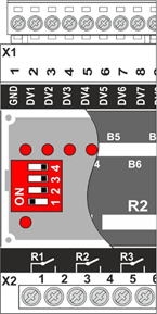
By default, each DV2 module has the basic communication address ADR = 1 set (see figure below).
The user can set communication addresses in the range 1 to 15 using bits of the 4-pole switch on the module board. Address 0 is not permitted. The address is set in binary, ie as the sum of the weight of the closed bits.
Adresa
Bit/váha | 1 | 2 | 3 | 4 | 5 | 6 | 7 | 8 | 9 | 10 | .. | 15 |
1. / 1 | 1 | 0 | 1 | 0 | 1 | 0 | 1 | 0 | 1 | 0 |
| 1 |
2. / 2 | 0 | 1 | 1 | 0 | 0 | 1 | 1 | 0 | 0 | 1 | 1 | |
3. / 4 | 0 | 0 | 0 | 1 | 1 | 1 | 1 | 0 | 0 | 0 | 1 | |
4. / 8 | 0 | 0 | 0 | 0 | 0 | 0 | 0 | 1 | 1 | 1 | 1 |

DV2 module addressing
Manual control
The DV2 module does not have its own buttons for manual relay control. It can only be switched on via the control station to which the unit is connected.
The relay can be switched either via the station keypad (Manual control / Relay menu) or via SMS (if the control unit contains a built-in GSM module).
Mechanical design
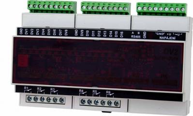
The DV2 unit is designed for mounting on a 35mm DIN rail in a switchboard and has a width of 9 standard modules.
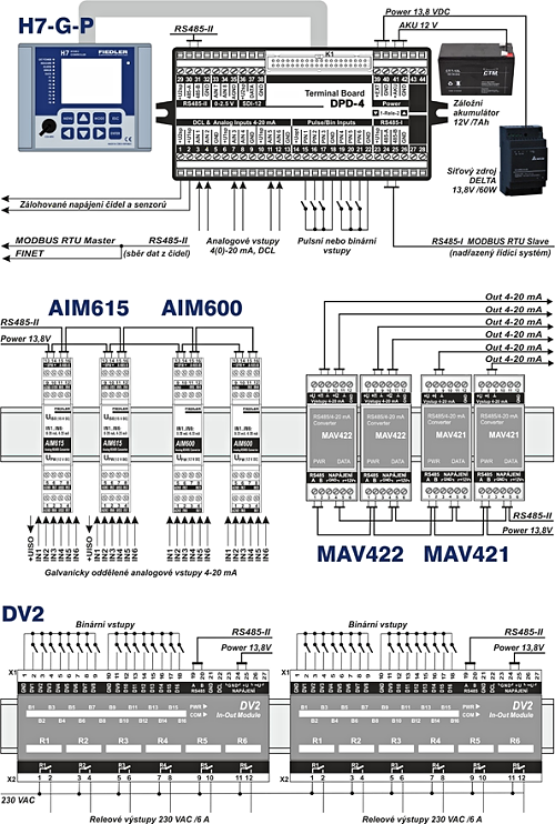
Example of connecting I/O modules to the H7 unit
Technical parameters
Binary inputs | 16 inputs; idle state UIN = 5 V; switching UIN <0.5 V, Rmax <250 Ω |
Binary outputs | 6 relays, switching contact 230 VAC / 5 A; non-inductive load |
RS485 | Channels K1, K2 to RS485; MODBUS RTU or FINET protocol |
Com. address | 0 + switch on board (1 to 15) |
Power voltage | 10 to 26 V DC / I < 250 mA |
Temperature range | -25 °C to +60 °C |
Dimensions / IP | 109 x 160 x 58 mm / IP 20 (width 9 modules, DIN rail) |
Main menu
- Solutions
- Tap water treatment
- Dispatching accessible via the Internet
- Remote water meter reading
- Monitoring of water leak
- Measurement of qualitative water parameters
- Measurement in Water Supply Network
- Pressures and flows regulation
- Controlling of water pumps and water reservoirs
- Controlling technology of waste purification plants
- Flow processing into charts
- Waste water treatment
- Monitoring of running and technology of WWTP
- Control technology of WWTP
- Measurement of waste water flow
- Dissolved oxygen measurement and aeration blowers control
- Measurement of chemical parameters of water
- Local control of pumping stations
- Remote control of pumping stations
- Root zone waste water treatment plants
- Dispatching accessible via the Internet
- Processing of measured flow data
- Water level monitoring
- Flood warning system
- Environmental monitoring
- Water level and flow monitoring in small water-courses
- Temperature measurement in bore holes and water basins
- Monitoring of soil humidity and temperatures
- Measurement of rain-fall quantity and intensity
- Level measurement in boreholes and remote data collecting
- Measurement of water temperature and conductivity in boreholes
- Measurement of well yield – pumping tests
- Water-level regulation in boreholes
- Capacity and intensity of drainage water
- Thermal balance in ecological constructions
- Meteorological stations
- Relative humidity and air temperature, rainfall, global radiating, atmospheric pressure, speed and direction of wind
- Satellite transfer while the GSM signal is unavailable
- Meteorological stations for agriculture and research institutes
- Extension of meteorological stations about special sensors
- Different type of tower constructions
- Data transfers into the Internet
- Special kinds of graphs for visualization
- Irrigation control systems
- Data collecting and processing
- Data hosting on the server
- Software MOST
- Parameterization of stations via the Internet
- Transferring of measured data into a current dispatcher programme
- Visualization and processing of data
- Data exports from the server into the PC
- Overview reports working-out and printing
- An automatic emails sending
- Types of SIM cards
- Operating costs of the telemetric station
- Industrial applications
- Tap water treatment
- Products
- Monitoring and control units for water supply
- Small telemetric stations and data loggers
- Smart Metering - remote meter readings
- Water level meters
- Hydrostatic level meters
- Radar level meters
- Ultrasonic level meters
- Level gauges for wells, boreholes and reservoirs
- Level float switches
- Equipment for pumping tests of boreholes and wells
- Local Warning Systems
- Flow meters for open channels
- Water quality sensors
- Meteorological stations and measuring sensors
- Accessories for control units and data loggers
- Boxes and cabinets for telemetry and control units
- Gel accumulators, batteries and backup sources
- AC power supplies and battery chargers
- Photovoltaic solar panels
- Antennas and extension cables
- Sensor cables, connectors and connecting expanders
- Communication signal converters and communication cables
- Mechanical mounting elements
- Industrial and residential water meters
- Server software and services
- References
- Support & Download
- About us
- Monitoring
- Datahosting
- OPTIMA Control unit
Download
Application
no related solutions


